Do You Know Heterojunction Technology (HJT) Solar Panels?


What is HJT technology? Heterojunction technology (HJT) is a N-type bifacial solar cell technology, by leveraging N-type monocrystalline silicon as a substratum and depositing silicon-based thin films with different characteristics and transparent conductive films on the front and rear surfaces respectively.

Combining with the benefits of crystalline silicon and amorphous silicon thin-fim technologies, HJT technology has excellent photoabsorption and passivation effects, as well as outstanding efficiency and performance. HJT panels are one of the technologies to improve the conversion rate and power output to the highest level, also represent the trend of the new generation of solar cell platform technology.


Why choose solar panels with HJT technology?

1. High conversion efficiency:


The homojunction cell type used in PERC technology uses crystalline silicon for the PN junction. Compared to conventional crystalline silicon solar cells using PERC technology, HJT solar panels are unique. HJT is a junction composed of two unique semiconductor substances.

It functions similarly to conventional solar cells, but the HJT cell is more effective at converting sunlight into electricity thanks to a thin layer of amorphous silicon.Currently, the average PERC efficiency of many PV manufacturers is over 22%, and the average HJT efficiency is over 22.5%.

In addition, HJT solar cells are made to have a module bifaciality of over 93%, which means they can produce electricity from both sides of the module. For instance, the Swiss company Ecosolifer has created a commercial bifacial HJT solar cell with a 24.1% efficiency.

HJT High conversion efficiency

2.Low temperature coefficient:


Compared to conventional crystalline silicon cells, thin-film solar energy produced by HJT solar panels has a lower temperature coefficient. At temperatures below 200 °C, HJT solar panels have an efficiency of over 23%.

Additionally, they have a low temperature coefficient of -0.2%/K, which boosts the efficiency and output of photovoltaic systems while lowering their cost.

This indicates that HJT solar panels can function effectively even in warm environments, enabling them to generate more energy in hotter environments. As a result, large-scale power generation using these high-performance cells is made possible.


3. Fewer production steps:


HJT solar panels are produced with fewer process stages than conventional solar panels made with PERC technology, which facilitates a smoother production process. HJT solar panels require only 8 processes for the production of solar photovoltaic modules as opposed to the roughly 13 processes needed by PERC technology. As a result, it is becoming more financially feasible, which is encouraging for the development of solar energy. This is because the price of the required equipment is continuing to drop.

HJT cells

4. Long service life:


HJT solar panels are renowned for their toughness, which means they last longer and require less upkeep, which lowers costs. The typical lifespan of solar panels is 25 years. However, under normal circumstances, HJT solar panels can last up to 30 years.

This is due to the protective barrier function of the amorphous silicon layer, which slows degradation and prevents the emergence of the PID effect. HJT batteries have a longer life as a result.

HJT


What is the HJT technology’s development trend?


The market’s most well-liked and desirable solar cell technology is PERC technology. It is regarded as the least complicated option because upgrading the production line only necessitates the addition of new machinery. The production of HJT solar panels, however, necessitates the acquisition of an entirely different set of production tools.

When it comes to solar cell development, HJT solar panels are far more effective and sophisticated than solar panels using PERC technology. Because of the high power generation efficiency of HJT solar panels, cell manufacturers and suppliers are becoming more and more interested in them. The future market will determine customer preferences, which will be a major factor in the development of HJT solar panels.

The solar industry is undergoing a revolution thanks to HJT (Heterojunction) technology, which increases energy output while also improving efficiency. To get around the drawbacks of conventional solar panels, HJT solar panels combine amorphous and crystalline silicon layers. This makes a variety of solar energy applications possible.

How much electricity can a 25KW solar power system standard generate per day?

How many kWh of electricity a  25KW solar power system can produce in a day depends on many factors, including light intensity, temperature, season, and shade. The following will introduce in detail the calculation formula of the standard daily power generation of a 25KW solar power system and the impact under different circumstances. In different regions and different seasons, the sunlight duration and the conversion efficiency of solar panels will change, so the daily power generation will also vary.


1. The influence of light intensity on power generation

Light intensity is one of the key factors affecting the power generation of solar power system. Light intensity refers to the light intensity per unit area, usually in watts per square meter (W/m²).

Daily power generation (kWh) = 25kW x light intensity (W/m²) x power generation efficiency x running time (hours)

If the light intensity of a 25KW solar power system is 1000W/m², the operating time is 8 hours, and the power generation efficiency is 15%.

Daily power generation (kWh) = 25kW × 1000W/m² × 15% × 8h = 30kWh

If the light intensity drops to 700W/m², the power generation will decrease accordingly:

Daily power generation (kWh) = 25kW × 700W/m² × 15% × 8h = 21kWh


2. Effect of temperature on power generation

Temperature is also one of the factors that affect the power generation of solar system. When the temperature rises, the power generation efficiency of solar cells will decrease, thereby affecting the power generation of solar system. Generally speaking, when the temperature increases by 1°C, the power generation of solar system will decrease by 0.4-0.5%.

Daily power generation (kWh) = 25kW x light intensity (W/m²) x power generation efficiency x running time (hours) x (1-0.004 x (temperature-25))

If the light intensity of a 25KW solar power system is 1000W/m², the operating time is 8 hours, the power generation efficiency is 15%, and the temperature is 25°C.

Daily power generation (kWh) = 25kW × 1000W/m² × 15% × 8h × (1-0.004 × (25-25)) = 30kWh

If the temperature rises to 35°C, the power generation drops accordingly:

Daily power generation (kWh) = 25kW × 1000W/m² × 15% × 8h × (1-0.004 × (35-25)) = 27kWh

It can be seen that temperature has a significant impact on the power generation of solar power system.


3. Seasonal influence on power generation

Seasons also have an impact on the power generation of solar power system. Generally speaking, the higher of light intensity in summer, the power generation will increase accordingly. While the lower light intensity in winter, the power generation will decrease accordingly.

Daily power generation (kWh) = 25kW x light intensity (W/m²) x power generation efficiency x running time (hours) x seasonal coefficient

The seasonal coefficient is generally between 0.8-1.2. For example, when the light intensity is 800W/m², the operating time is 8 hours, and the power generation efficiency is 15%, the seasonal coefficient is 1.2 in summer and 0.8 in winter.

Daily power generation in summer (kWh) = 25kW × 800W/m² × 15% × 8h × 1.2 = 23.04kWh

Daily power generation in winter (kWh) = 25kW × 800W/m² × 15% × 8h × 0.8 = 15.36kWh

It can be seen that seasonal factors also have a greater impact on the power generation.


4. The impact of shadow occlusion on power generation

If the photovoltaic power plant is blocked by shadows, its power generation will decrease accordingly. Shading will affect the power generation efficiency of some solar cells, thereby affecting the overall power generation.

Daily power generation (kWh) = 25kW x light intensity (W/m²) x power generation efficiency x running time (hours) x shading factor

Assume that the shading coefficient of the solar system is 0.9, the light intensity is 1000W/m², the running time is 8 hours, and the power generation efficiency is 15%.

Daily power generation (kWh) = 25kW × 1000W/m² × 15% × 8h × 0.9 = 24.3kWh

It can be seen that even if only a part of the photovoltaic cell is shaded, its power generation will be affected.

According to the above, the standard daily power generation of a 25KW solar power system can reach 30-35kWh under ideal conditions. However, the actual situation is affected by many factors, so the power generation may be reduced. For example, if it is cloudy or the temperature is too high, the power generation may be reduced accordingly. Therefore, in order to improve the power generation efficiency of solar power system, it is necessary to avoid shading as much as possible, and to plan well in terms of site selection and components.

Select your solar power system from here: https://www.higonsolar.com/solar-solution

N-type or P-type solar Panel?

What is the N-type and P-type Solar cell?

The average solar buyer probably is not paying attention to whether solar panels are made with p-type or n-type solar cells. But since you know there has N-type and N-type solar panel, you may start wondering what exactly difference between them and how they may affect solar panel buying in the future.  A conventional crystalline silicon (c-Si) solar cell is a silicon wafer doped with various chemicals to encourage power production. The main difference between p-type and n-type solar cells is the number of electrons. A p-type cell usually dopes its silicon wafer with boron, which has one less electron than silicon (making the cell positively charged). An n-type cell is doped with phosphorus, which has one more electron than silicon (making the cell negatively charged).

Compared with P-type polycrystalline silicon wafers, the technical performance advantages of N-type monocrystalline silicon wafers are very firm:

  • N-type cells/modules unaffected by boron-oxygen-related photodegradation;
  • N-type substrates are more tolerant of common metallic impurities such as iron;
  • N-type silicon wafer-based cells allow for bifacial cell designs that can absorb backside illumination to produce higher power;

It is also worth noting that N-type monocrystalline silicon wafers provide the substrate for a truly high-efficiency cell structure.


What is the future of N-type and P-type?

Looking ahead, it is more difficult to improve the efficiency of PERC cells,and the N-type technology with higher efficiency, lower attenuation rate and better low-light performance is recognized as the next generation photovoltaic cell technology. As far as the specific technical route is concerned, the three cell technologies of TOPCon (tunneling oxide passivation contact), HJT (intrinsic thin film heterojunction) and IBC (interdigital back contact) are widely sought after. Among them, TOPCon and HJT technology are the focus of industrial investment and market attention.

Considering the cost, TOPCon is one step ahead. It is reported that the theoretical maximum efficiency of TOPCon can reach 27.1% (single-sided) / 28.7% (double-sided). The advantage of TOPCon is that the production line is compatible with the existing PERC production line, which has also become the preferred iteration technology for large PERC capacity producers. With mass production, TOPCon companies claim that the cost of battery modules is expected to be equal to that of PERC within a year, and the cost of BOS will be significantly reduced.

According to the forecast of CPIA, in 2030, the market share of N-type batteries may reach about 56%, and the prospects are very broad.

N-Type Panels Four Facts You Need To Know

Five fast facts to bring you across all things N-type.


FACT #1: N-type solar cells were developed before P-type

The first solar cell was developed in 1954 – and it was in fact an N-type cell. So why did P-types become so popular? 

When solar PV technology was starting out, most of it was being used by space agencies. In space, P-type cells proved to be more resistant to radiation damage than N-types. Hence, more focus and resources were put on P-type cell development, leading to their dominance in today's market.


FACT #2: N-type cells are more efficient than P-type

One of the main differences in the engineering of N-type panels vs P-type panels is their 'doping’. Doping refers to the addition of chemicals to the crystalline silicon to promote power production.

An N-type solar cell is doped with phosphorus, which has one more electron than silicon, making the cell negatively charged (hence the 'N' in N-type).

A P-type cell is doped with boron, which has one less electron than silicon, making the cell positively charged (the 'P' in P-type).

When boron is exposed to light and oxygen, it causes Light Induced Degradation (LID). This happens as soon as solar panels are installed and decreases anywhere between 1% and 3% depending on the brand of the panel.

N-type panels don't use boron and therefore aren't affected by LID. It means better efficiency and improves the useful life of the panel. 


FACT #3: N-type cells are more expensive than P-type – however this is expected to change

The downside to N-type panels in today's market is cost. They are more expensive to make and therefore more expensive to buy. With more focus and resources on P-type development, they quickly became more cost effective to produce for manufacturers and cheaper to purchase for end users. Investment into N-types was left behind.


FACT #4: N-type are projected to take over P-type in market share by 2024/25

Industry estimates suggest that N-type panels will be the solar industry's dominant technology by 2024/25 as engineering and manufacturing processes evolve and costs come down.


For a simple explanation of the manufacturing differences between the N-type and the P-type, check out our infographic:

Tips for solar panels cleaning

 
Solar panels are widely used to generate electricity, but their performance can be affected by contamination such as dirt, bird droppings, and pollen. 🐦

Here are 3 tips to clean solar panels:

1. Prioritize safety by shutting down the system before cleaning and using safety ropes for roof-mounted panels.

2. Use gentle cleaning methods to avoid scratching the surface. Clean water, detergent, and a soft brush are ideal tools for the job.

3. Opt for early morning or evening cleaning when the panels are cooler. Cleaning while the sun is shining can lead to quick water evaporation and residue buildup.

#HigonSolar, we are committed to providing customers with reliable and durable products. Regular solar panel cleaning can ensure long-term benefits for your solar system's performance

#solarenergy #solarpanelclearn #solarpv

What is battery C rating?

What Is Battery C Rating?

The battery C rating can be defined as the measure at which a battery is discharged relative to the maximum capacity of the batteries.

A battery’s charge and discharge rates are controlled by battery C rating. In other terms, it is the governing measure of at what current the intended batteries is charged or discharged and how quickly that occurs.

The capacity of a battery is generally rated and labeled at 3C rate(3C current), this means a fully charged battery with a capacity of 100Ah should be able to provide 3*100Amps current for one third hours, That same 100Ah battery being discharged at a C-rate of 1C will provide 100Amps for one hours, and if discharged at 0.5C rate it provide 50Amps for 2 hours.

The C rate is very important to know as with the majority of batteries the available stored energy depends on the speed of the charge and discharge currents.

Why The C Rating Are Different Between Different Battery?

1C means 1 hour discharge time.

2C means 1/2 hour discharge time.

0.5C means 2 hour discharge time.

In many applications, the battery rate is very important. For example, we want the car to be fully charged within half an hour, instead of waiting for 2 hours, or even 8 hours. What is cause influence to the battery C rating?

There are two limitations to how fast a battery can be charged-thermal heating and mass transfer limitations.

Thermal heating occurs because the internal resistance of the battery generates excessive heat, which must be dissipated to the environment.

When charging occurs at very high currents, the heat generated within the battery cannot be removed fast enough, and the temperature quickly rises.

Mass transfer of Li+ ions during fast charge results in diffusion limiting current even if the electrodes are made of nanoparticles with high surface area. While the high surface area allows sufficient rate of lithiation or de-lithiantion, the Li+ diffusion through the cross-sectional area of the electrolyte within the separator is limited. It is quite possible to fast- charge for a limited time restricted to the Li-ions already presented in the electrolyte withing the electrode. This unssteady state diffusion can last until the Li+ ions are depleted and their supply is limited by the cross-sectional area of the battery.

This mass transfer limitation occurs because the transference number of Li+ is smaller than 1. While Li+ions carry a fraction of the current in the electrolyte, they carry 100% of the current at the electrode; thus depletion of Li+ occurs near the anode, resulting in diffusion limiting current. Any attempt to surpass the limiting current results in solvent decomposition, heating and deterioration of the battery.

So different material battery will have different rate, the typical NCM lithium battery C rating is 1C, and maxium C rate can reach 10C about 18650 battery. the typical LiFePO4 lithium battery C rating is 1C, and the maxium C rate can reach 3C about LiFePO4 prismatic battery.

Battery C Rating Chart

Below chart shows the different battery C rating and their discharge time.When we caculate them, the battery C rating should use same caculation as the same energy.
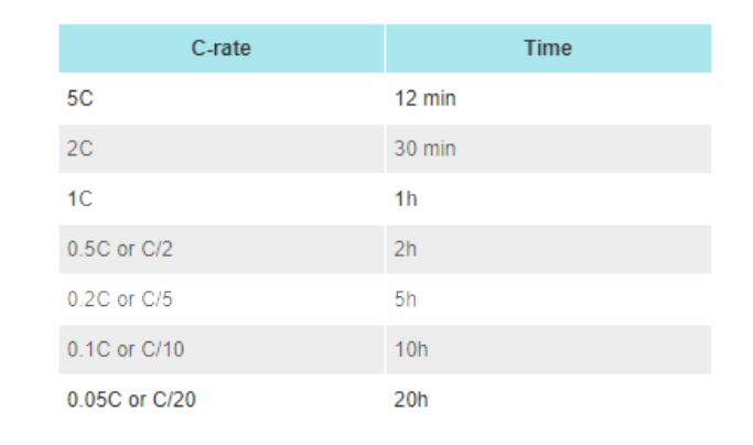
Battery C Rating Chart

For most of lithium battery, here is the picture to show the discharge curve in different C rate.
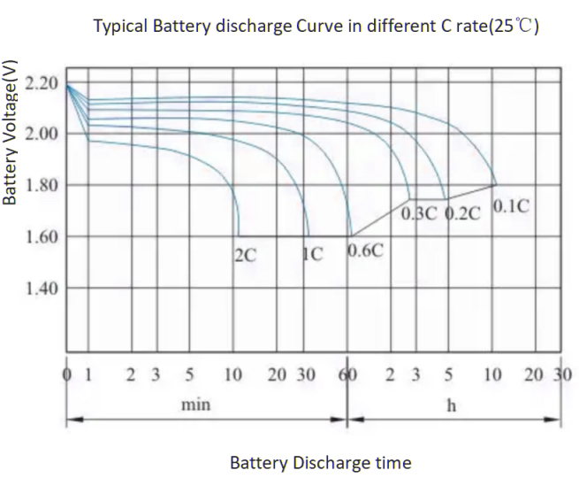
Battery discharge Curve in different battery C rating
Battery Discharge Curve In Different Battery C Rating

For most lead-acid batteries, we should know that even for the same battery, the battery capacity at different battery C rating is different. To get a reasonably good capacity reading, lead acid batteries manufacturers typically rate lead-acid batteries at 20 hours(A very low 0.05C). The following is the discharge capacity of a Trojan 12V135Ah battery at different rates.

Lead acid battery capacity in different battery C rating
Lead Acid Battery Capacity In Different Battery C Rating

How To Calculate The C Rating For The Battery?

A battery’s C rating is defined by the time of charge and discharge.

C-rate is an important information or data for any battery, if a rechargeable battery can be discharged at that C rating, a 100Ah battery will provide about 100A, then the battery has a discharge rate of 1C. If the battery can only provide a maximum discharge current of about 50A, then the discharge rate of the battery is 50A/100Ah=0.5C.

C-rate (C) = charge or discharge current in amperes (A) / rated capacity of the battery(Ah)

Therefore, calculating the C rating is important for any battery user and can be used to derive output current, power and energy by:

Cr = I/Er

Er = Rated energy stored in Ah

I = Charge/discharge current in A

Cr = C rate of the battery

t = Charge/discharge duration

Calculate charge and discharge time

t = Er / I

100Ah Lithium Battery C Rate Example

For same 100Ah lithium battery,

1C means 100Ah*1C=100A discharge current available.

1C means 100Ah/100A=1 hours discharge time Capable.

It means the battery can be use for 60minute (1h) with load current of 100A.

2C means 100Ah*2C=200A discharge current available.

2C means 200Ah/100A=0.5 hours discharge time Capable.

It means the battery can be use for 30minute (0.5h) with load current of 200A.

0.5C means 100Ah*0.5C=50A discharge current available.

0.5C means 100Ah/50A=2 hours discharge time Capable.

It means the battery can be use for 120minute (2h) with load current of 50A.

Sometimes analyzer capacity readings are given as a percentage of the nominal rating. For example, if a 1000mAh battery can supply this current for about 60 minutes, read 100%. However, if the battery lasts only half an hour before the cut-off point, the displayed value is 50%. Sometimes a brand new battery can provide more than 100% capacity. The battery can be discharged using an analyzer which allows you to set your favorite C rate. If the battery is discharged at a lower discharge rate it will show a higher reading and vice versa. However, you should be aware of differences in battery analyzer capacity readings for different C rates, which are related to the internal resistance of the battery.

What Are The Effects Of C Rating On Lithium-ion Batteries?

After we caculated above, we know more higher the C rating on a battery, the faster the energy can escape the batteries to power the application. The C rating on any battery depends on its application. Because some electronics require large amounts of power supply thus need batteries with high C ratings, For example, the motorcycle starter, you only needs needs a few seconds to power the motors quickly. But for some application, the discharge time only need need low C rating, Such as the soalr light, you want them to power for whole night or several nights.

What Is The C Rating Of My Battery?

You'll usually find the battery's C-rate on the battery's label and on the battery's data sheet. Different battery chemistries sometimes show different battery C rates.

Generally speaking, Lithium iron phosphate batteries typically have a discharge rate of 1C

NCM batteries typically have a discharge rate of 3C

Lead-acid batteries are generally rated for a very low discharge rate, typically 0.05C, or 20 hour rate.

If you cannot find the battery C rating on the label or datasheet, we recommend contacting the battery manufacturer directly.

In Conclusion

The C-rate is a unit used to identify a current value/discharge time of a lithium-ion battery under different conditions. Since you have had a clear view of what the C rating is , and what it stands for in a battery, you will need to include it in your next selection for batteries to get the best out of what you settle for.

What is shingled solar panel ?

Shingled solar cells are solar cells which are cut into typically 5 or 6 strips.  These strips can be overlaid, like shingles on a roof, to form the electrical connections.  The strips of solar cells are joined together using an electrically conductive adhesive (ECA) that allows for conductivity and flexibility.

Shingled solar cell


Shingled solar cell – end elevation


This allows the cells to be connected differently to conventional solar panels, in that, there are no busbars (ribbons) required and the solar cells can be joined together resulting in no gaps between the solar cells.


Shingled solar modules can also be wired differently to conventional solar panels.  Typically, solar cells in conventional solar panels are wired in a series of strings whereas the solar cells in shingled panels can be wired in parallel configuration.


What are the advantages of shingled solar panels?

Essentially the three key advantages of the shingled solar panel design are they produce more power, improve reliability and are aesthetically pleasing.


1. Increased energy harvest

Higher power per square metre

The shingled solar cells do not require busbars across the top of the cells so more of the solar cells are exposed to sunlight.  The cells do not need to be spaced apart like in conventional solar panels so the solar panel area can produce more energy.


Comparison between conventional solar panel and Solaria shingle solar panel


Less energy loss due to shading

Conventional solar panels have the individual cells wired in series so when a part of the solar panel is shaded it can have a significant effect on the level of power output.  By configuring the solar cells in shingles, they can be wired in groups and configured in parallel which significantly reduces the losses caused by shading.

Current flow comparison


Below are some examples of shading and losses for a conventional solar panel and a shingled panel.  The Shingled panels have greater performance except for the vertical shading example.


Outdoor shade testing over a 70-day period has shown that the  shingled solar panel performs between 37 to 45% better than conventional solar panel designs.


2. Better reliability


Low busbar failures

Shingle solar panels do away with approximately 30 metres of busbar and soldered joints that is required on conventional solar panels, so busbar failures are reduced.


Better mechanical performance

Static and dynamic load tests show that the shingle approach is more resistant to failure due to external forces being applied to the solar panel compared to conventional solar panels.


3. More attractive

Shingled solar panels have no visible circuitry which give them clean simple look providing superior street appeal.


What is the function of the isolation transformer in solar inverter?

  1. Isolation transformer is a device designed to achieve complete electrical insulation between its primary and secondary sides, effectively isolating the circuit. It prevents direct electrical continuity between the input and output, enhancing safety and protecting both equipment and individuals.
  2.  
  3. 1. Isolation Function: The inverter operates by inverting through IGBT power devices, which generate a significant amount of third harmonic and its multiples. These harmonics pose a serious threat to grid pollution. By incorporating an isolation transformer (primary winding in delta connection, secondary winding in star connection), the third harmonic and its multiples can be effectively filtered out. When high-order harmonic currents pass through the primary winding of the isolation transformer, a large inductive reactance is generated in the winding. As a result, the ripple current becomes very small, ensuring that harmonic currents on the secondary side of the isolation transformer are minimized and providing a clean power source for the load.
  4.  
  5. 2. Increased Short Circuit Impedance: In the event of a short circuit fault on the load side, the existence of impedance in the secondary winding of the isolation transformer significantly reduces the short-circuit current. This reduction helps minimize the impact and damage caused by short-circuit currents on the inverter.
  6.  
  7. 3. Providing Neutral Point for Output Power: As the three-phase AC power output by the inverter lacks a neutral point, installing an isolation transformer on the output side is necessary to obtain a neutral point and achieve a 220V AC power source.
  8.  
  9. 4. Complete electrical insulation between the primary and secondary sides, thereby isolating the circuit. Additionally, it takes advantage of the high-frequency loss characteristics of its core to suppress the transmission of high-frequency interference into the control circuit. Isolation transformers are used to float the secondary side with respect to ground, suitable for scenarios with a limited power supply range and short line lengths. In such cases, the system's ground capacitance current is insufficient to cause harm to individuals.
  10.  
  11. 5. The primary function of an isolation transformer is to provide electrical isolation, serving both equipment protection and, importantly, personal safety. It isolates hazardous voltages, with the small capacitance coupling between the input and output of the isolation transformer having a suppressive effect on disturbances caused by lightning, discharges, grid switching, motor starts, and other grid bursts. From this perspective, isolation transformers serve as effective noise suppressors for power sources, providing equipment protection. Regarding personal safety, it ensures the protection of individuals operating the equipment. Since the electromotive force of an isolation transformer is obtained through secondary induction and does not form a circuit with the primary side (which forms a circuit with the ground), it eliminates the risk of electric shock.
  12.  

Why Solar Panels Output is Always Lower Than Expected

At this point, it's safe to assume that everyone knows the products they buy never do their advertised qualities or quantities any justice. Be it the bag of potato chips which has more air than chips or a car that just won’t touch the mileage its manufacturer claims. We're used to stuff performing below expectations and don’t mind it either.

Solar panels on the other hand, are usually excluded from such handicaps. Most consumers go into a solar purchase expecting their panels to produce as many watts as their sticker states, at least in the best of conditions.

Unfortunately, solar panels are no different from any other consumer product in this sense. In fact, don't be surprised at all if you find your panel’s output well below its rated capacity even on the brightest and sunniest of days when they are sparkling clean.

Here's why this happens.

What Can You Realistically Expect from Your Solar Panels

So, that 300 watt solar panel you've been researching probably doesn’t dishout 300 watts of power. But, just what is its realistic upper limit here? The answer depends on a few key factors.

Firstly, a solar panel's rated output is decided through rigorous laboratory testing. These tests are done in perfect conditions devoid of dust, clouds or any other pollutants with light shining directly on the panels at a perfect 90 degree angle. We've covered this in greater detail in our post on solar panel quality.

At first glance, such tests may seem deceptive since ideal conditions are rare, if not impossible. But, the objective of a solar output test is to determine the absolute power a panel can produce, which is an important figure to have.

So, how much of this power can you actually expect to harvest? Solar panels usually achieve only around 80% of their rated peak capacity, but may fall lower. A number of factors contribute to such losses.

What Causes Solar Power System Losses

Losses in usable power start to occur as the light falls on a solar panel. For the purposes of this article, we're going to ignore power loss due to environmental factors such as clouds, shade, dust, etc and focus on losses that are inherent in a solar power system due to its physical limitations. Here's a rundown of how it happens at each level:

Mismatch losses

Also known as the “mismatch effect”, power losses here are caused if solar cells in an array have different properties, resulting in inconsistent voltages. Mismatches can result in serious power losses since the entire system defaults to the output of the lowest performing solar cell.

Besides low power output, excess electricity trapped in the solar module's electric circuit is converted into heat that can further damage the solar modules. Mismatch losses can result in around 2% power loss.

Temperature loss

Solar cells perform best below 25 degrees celsius, which is also what the temperature they are tested against. The catch here is that these figures refer to the temperature of the cells and not that of ambient air surrounding the panels. So, the panels themselves can get much hotter than 25 degrees even if the ambient temperature is a cool and breezy 20 degrees.

A solar panel's power output can drop drastically as it gets hotter than 25 degrees. Power loss due to heat is measured as “Pmax”, which tells us how much a solar panel's electricity production drops per degree rise in temperature. For example, if a solar panel's Pmax is -0.45%, then that's how much electricity we lose per one degree celsius.

Temperature accounts for the majority of a solar panel's output losses and can range from 10% to as much as 25% in very hot conditions. Since mean temperature in most Australian cities can reach well over 30 degrees celsius during summer months when we have the most sunlight, the solar panels will also experience the greatest power loss here.

Light-induced degradation (LID)

LID typically occurs during the first few days after a solar installation and causes power loss due to build up of boron-oxygen compounds in the solar cell's silicon base. Some solar cells are more predisposed towards LID than others. LID accounts for 0.5% to 1.5% of power loss in photovoltaic systems.

P-type monocrystalline solar cells have higher oxygen content and are doped using boron and accept electrons, which makes them more susceptible to LID.

Multicrystalline solar cells are not as efficient as monocrystalline cells, however have less oxygen making them resistant to LID. Similarly, N-type silicon wafers are doped with chemicals that release electrons making them impervious to LID.

Cable and wiring losses

Solar panels are a collection of photovoltaic cells stacked in an array. These arrays feed into a wire that runs from the panel into the inverter. Since no wire is fully efficient, part of the power flowing through it is lost as heat.

For most solar power systems, cable related power degradation accounts for around 2% of the system's total loss, which can be brought down to 1% by using thicker wires or positioning the system such that it requires shorter wires to reach the inverter.

DC to AC Loss

Solar panels produce DC current that's unusable by household appliances. A solar inverter then converts that DC power into usable AC electricity which is fed into your home’s electrical circuit and the grid.

Since solar inverters are around 93% – 96% efficient, a portion of DC power being fed into them will be lost as heat. The exact amount of electricity lost will depend on your inverter make, and whether it’s oversized or not.

Oversized inverters (or, inverters that are rated for a higher output than the solar power system's total output) are more efficient than those that are matched to their panel's output.

Inverter Clipping

Inverter clipping happens when the DC power input from the panels is greater than its rated capacity. In such a case, the inverter “clips” or derates the overall output to match its own capacity, causing a loss in power.

How Can You Maximize Your Solar Power System's Output

The reasons for power loss we've discussed above are mostly unavoidable, because physics. However, we can also bring down such losses by designing efficient solar power systems.

For example, selecting solar panels with low or no LID potential, using sufficiently thick wires and cables, strategically sizing the inverter to mitigate clipping and positioning the solar panels such that they receive as much direct sunlight as possible can all help increase the system's output.

Will persistent summer heat damage home photovoltaic equipment?


Marching towards August, the temperature remains high💦. While we are standing with the continuous summer heat, are you curious about the 'feelings' of your home PV equipment? Can they survive under ongoing high temperatures? Let's find out🧐!

Since PV solar panels do not contain circulating water, they can evacuate heat from each side of the panel, so they do not bear the risk of overheating. However, high temperatures can influence the efficiency of solar panels. So, how can we test solar panels for power output? The standard practice is at 25°C.

If a panel is rated to have a temperature coefficient of -0.34% (PERC) per °C, that panel's output power will decrease by 0.34% for every degree the temperature rises above 25°C (77°F). Although that number may sound small, the surface temperature of a dark roof in summer can be significantly higher than 25°C – imagine an asphalt road surface on a hot summer day. The small percentage of output power loss for each degree of heat compound.

Choosing the right solar panels and the right solar system size, together with high-quality installation, will help reduce the effects of heat.

So, be relaxed, be prepared, and enjoy your summertime!

#HigonSolar #SolarLearnHub #solarFAQ